1. Provide the updated computer drawing for your individual RG setup.
2. Explain your setup.
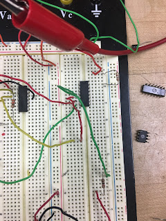
The circuit starts with the force sensing resistor triggering a transistor to switch channels and using the diode the relay sends current to pin 2 from the pin it switched to in order to continue to flow after the transistor no longer sends any voltage. From here, voltage is sent to the X-OR gate where it is met by another input from the other very similar portion of the circuit. While the first relay sends a 1 to the x-or the x-or sends a signal to the op-amp that is then amplified and sent to the dc motor which pulls a lever on the built set-up pictured below that lets the marble run. Once the marble reaches the bottom it hits another force sensing resistor that triggers the second relay and sends a 1 to the x-or gate which then has inputs of 1/1 and then stops giving output to the motor. The transistor after the force sensing resistor can be used to trigger the second part of the RG setup.
3. Provide photos of the circuit and setup.
 |
| Marble tower, Physical component |
 |
| Picture of start |
 |
| Picture of XOR gate |
 |
| Complete picture of circuit |
4. Provide at least 2 new videos of your setup in action, one being a failed attempt.
Failure
Success
5. What failures did you have? How did you overcome them?
Failures this week occured connecting our circuits. in the video it is shown how after my circuit ends, angels doesnt start. this was happening because an issue with the op amp and the voltage my circuit provided it. The voltage my circuit was sending his would drop due to being wired up in series so the connection acted as a voltage divider. after fine tuning input levels we eventually found inputs that allowed it to work and as shown, we had success and my circuit triggered his after my mechanical aspect ended.

I wonder if you also could have wired the op amp input in parallel to maintain a steady voltage, but that may cause problems with too much current being pulled from the power supply. I really like the mechanical stucture, it seems very reliable.
ReplyDeleteYou did not implement the timer yet, did you?
ReplyDeleteI haven't added the timer yet, I'm going to the lab today, tuesday, to add that component.
DeleteI liked how your RG are connected guys. I also like how Joe circuit start by applying a reasonable amount of force. Especially, when it comes to the group GR connections.
ReplyDeleteJoe, I like your mechanical part very much, but be still working if you use something other than the force sensing resistor.
ReplyDeleteI really like the idea the marble hits the other force sensor and stop the motor, your mechanical part looks great, I see the leaver wasn't pulled and I think using a smaller gate to hold the marble would be better. For your circuit part, I really liked how you used the relay to send signal to the XOR gate. I am using an Opamp and I also have the same problem, the XOR gate sends voltage to the Opamp but the output voltage of the Opamp decreases, I solved it by connecting the bigger resistor to the output and the smaller resistor to the input.
ReplyDeleteUsing two force sensing resistors may make your circuit seem a little simple. It may be interesting to replace one, and add another component that you don't already have. Your breadboard seems to have less wires than most others, but I am not sure why that is. From your description you seem to have a lot of components.
ReplyDeleteWithout the use of a timer in your circuit, I can imagine it being a little tricky to have your set up fall within the required time limit. However, your marble tower is quite impressive.
ReplyDeleteI enjoyed that both your mechanical designs used towers, both your circuits seem to mimic each other and use a lot of components, but other than that you both have great circuits.
ReplyDeleteI enjoyed the use of the XOR gate cutting power from the motor.